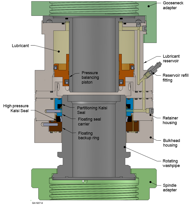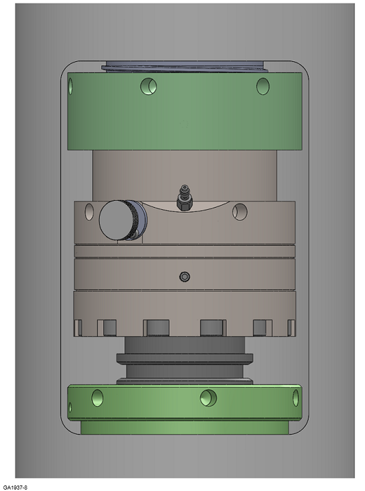
The washpipe assembly shown below has been developed for 7,500 psi service at 200 rpm, and has a three inch bore. In order to achieve this level of performance, the assembly separates the abrasive exclusion function from the pressure sealing function, provides a better way of accommodating washpipe misalignment and runout, and employs a new, plastic-lined high pressure rotary seal. The assembly fits within the space provided by a typical gooseneck support housing.
Hardware overview
One end of a sliding piston is exposed to the drilling fluid, and the other end is exposed to a seal lubricant. This arrangement causes the seal lubricant to have about the same pressure as the drilling fluid. The pressurized lubricant is communicated to a sealed region between a pair of rotary seals.
The upper rotary seal was developed to serve as a partition between the drilling fluid and the seal lubricant, and to exclude the abrasive content of the drilling fluid. This seal experiences little or no differential pressure. The lower seal was developed for extreme pressure lubricant retention, and is isolated from the abrasive content of the drilling fluid. Both seals incorporate hydrodynamic geometries that promote seal longevity by forcing a film of lubricant into the dynamic sealing interface.
The washpipe is rigidly mounted to the spindle of the top drive. Both rotary seals are mounted in seal carriers that have a journal bearing fit with the washpipe, and move laterally to accommodate washpipe runout. The lower seal carrier is designed to enhance the high pressure performance of the lower seal, and the upper seal carrier is designed to enhance the abrasive exclusion of the upper seal.
The lubricant reservoir
The sliding annular piston is located between a pressure housing and a guide tube, and together with them forms an integral lubricant reservoir filled with a relatively low viscosity oil-type lubricant.
The pressure of the drilling fluid acts on the lower side of the sliding piston, pressurizing the lubricant. A cross-drilled hole communicates the pressurized lubricant to a sealed region between the pair of rotary seals. The lower seal is isolated from the drilling fluid, and only has to retain the high pressure of the clean seal lubricant. The upper seal is isolated from high differential pressure, and only has to exclude the abrasive content of the drilling fluid.
The reservoir capacity, which is about 0.75 liter, is defined by the area and stroke of the piston. This capacity is designed to accommodate the slow loss of lubricant that results from the hydrodynamic pumping action of the rotary seals. This pumping action decreases at higher pressures and temperatures Although the recommended refill schedule is every one to two days, the reservoir is designed to last four days with the higher pumping rate associated with lower temperatures and drilling fluid pressures.
The partitioning seal
The partitioning seal is a 673-series Axially Constrained Kalsi Seal™. This type of seal was developed to overcome the challenges associated with excluding abrasives in the absence of differential pressure, and in the presence of low levels of potentially reversing differential pressure, and to be compatible with relatively low viscosity seal lubricants. To learn more about 673-series Axially Constrained Seals™, see Chapter C4 of the Kalsi Seals Handbook™.
The mounting ring for the partitioning seal
The partitioning seal is mounted in a floating seal carrier. On the lubricant side of the rotary seal, the carrier has a close-fitting journal bearing-type fit with the washpipe that locates the carrier laterally, and causes the carrier to follow the runout of the washpipe. On the drilling fluid side of the rotary seal, the carrier defines a carrier-to-washpipe extrusion gap clearance that is larger than the journal bearing clearance. The journal bearing fit on the lubricant side of the seal helps to maintain the extrusion gap clearance at a relatively constant value. This facilitates exclusion of the drilling fluid and reduces abrasive wear of the washpipe.
The pressure retaining seal
The pressure retaining seal incorporates a highly extrusion resistant plastic liner, and an innovative hydrodynamic geometry that is aggressive enough to lubricate the dynamic sealing interface despite the stiff nature of the plastic liner. This interfacial lubrication greatly increases the pressure-times-velocity (PV) capacity of the seal, compared to seals constructed entirely of elastomer. To learn more about Plastic Lined Kalsi Seals™, see Chapter C16 of our rotary seal handbook.
The mounting ring for the pressure retaining seal
The mounting ring for the pressure retaining seal is an axially force-balanced metal backup ring that also locates the seal laterally. The axial force balance situation is created by exposing equal areas on opposite ends of the backup ring to the same pressure. The lack of axial force imbalance leaves the backup ring free to follow shaft runout.
The backup ring has a tight, journal bearing fit with the washpipe that also serves as the extrusion gap for the pressure retaining seal. This floating backup ring arrangement is to our knowledge the best way to minimize the extrusion gap, which increases the pressure capacity of the pressure retaining seal. Because the seal and backup ring move laterally to follow washpipe motion, the seal is isolated from runout-induced radial compression changes. To learn more about floating backup rings, and how they work, see Chapter D17 of our rotary seal handbook.
Overall construction of the high pressure washpipe assembly
The pressure envelope of the washpipe assembly consists of housings that are stacked together, piloted with respect to one another, and secured by socket head cap screws (not shown). The precision pilots between the housings are axially short, which prevents binding. All static pressure seals are face seals, for ease of assembly and for reliable sealing in extreme pressure conditions.
Installing the washpipe assembly on a top drive
Much like conventional washpipe packing assemblies, this assembly is collapsed and inserted between the gooseneck and spindle. The adapter rings are then threaded to the spindle and gooseneck.
Contrast with previous generations of hydrodynamic washpipe assemblies
Unlike past washpipe assemblies designed by Kalsi Engineering, this one does not require external lubricators, lubricant overpressure, or pressure staging.
Contact us for additional information.


